Voltage
In the context of electronics, voltage is the difference in electrical potential between two reference points. A charge's electric potential energy is similar to gravitational potential energy, wherein if a positive charge is within the electric field of a negative charge, it will have increasingly less electric potential energy as it moves closer towards the negative charge, and vice versa with charge polarity inverted. Measuring a point's voltage is typically done relative to a common reference point, e.g. ground.
The "kinetic energy" from which electric potential energy is converted into is current, with a byproduct of thermal energy caused by either natural resistance, or through intentionally resistive components (like resistors) which purposely inhibit the flow of current.
Current
As described before, current is the result of actualising electric potential energy in a connected circuit. Current describes the rate of flow of charges through a conductive material at a certain point, so it can be represented differentially: Where $q(t)$ represents the cumulative number of charges having passed through a reference point in the conductor up until time $t$. The moment a power source with an active voltage differential across its terminals is applied to a complete circuit, it induces the electric field from which the charges in the conductive material begin to form current. The work necessary to maintain the potential difference across the terminals, and thus to maintain the current, is the sole responsibility of the power source by whichever mechanisms it does so.
Batteries
Note that in a battery, as the capacity dwindles towards zero, the voltage does not drastically decrease until the concentration of reactants which form the potential difference across terminals reaches a certain threshold. Additionally, since real batteries are not ideal, they carry internal resistance which is denoted on the packaging, leading to a measurable voltage drop-off at the terminals.
Electric fields
As described before, when a power source is connected to a complete circuit, an electric field is induced as the charges configure themselves in the most optimal path towards the negative terminal. The pressure causing them to "move" is the electric potential which is decided almost instantaneously based on the circuit components. A resistor would have a denser electric field, indicating more potential energy is transformed into heat energy as charge crosses through it, which is itself the purpose of a resistor.
Note that the optimal path is not already known, all paths of the circuit are "visited" in a sense, but the electric field quicky resolves its steady-state where the current is established according to our formulaic notions.
Resistors
Resistors decrease the electric potential between its ends, as it converts electric work into heat energy in a controlled manner, thus causing a voltage drop. Note that resistors tend to have less charge carriers than a regular conductive material, so it will constrict the current according to Ohm's law: In a simple circuit with a resistor in series with an ideal power source, the voltage drop will always be the same as the input voltage, as the electric field adjusts itself to whatever strength is necessary to push through the resistor, and so the current will be the only relevant consideration.
Voltage division
Two or more resistors in series must drop the voltage in a manner which results in the voltage drop equaling the voltage input $V_{in}$, therefore when you have two resistors of resistance $R_1$ and $R_2$ they must split the voltage in proportion to their resistance. Assuming that voltage drop-off is linearly proportional to resistance, we can derive the equations to figure out what the voltage would be between each ends of a resistor in this configuration.
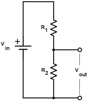
Since we have assumed voltage drop-off is linearly proportional to resistance, we have some $V_1 \sim R_1 \to V_1 = kR_1$; similarly, $V_2 = kR_2$, as we assume the constant of proportionality is the same between resistors, thus $\frac{V_1}{V_2} = \frac{R_1}{R_2}$. given that we have $V_{in} = V_1 + V_2$, we may solve for either voltage drop-off constant without loss of generality: Which accurately depicts what one's intuition would expect, i.e. that you are taking the proportionality ratio and scaling the input voltage against it to calculate the voltage drop-off for the particular resistor.
Current division
On the same branch, current division is possible with resistors when they are placed in parallel. Consider the figure below:
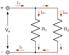 We have the given fact that $I_1 + I_2 = I_T$, from this we may derive the circuit resistance:
Since we have $I_T = \frac{V}{R_T}$:
And subsequently, we may resolve $I_1$ WLOG., given that we know the voltage drop-off is equivalent:
This can be generalised for any subcircuit which holds resistors in parallel, given that the voltage and resistances are known; the derivation is analogous, and simply extends as a result of the conservation of current: $I_T = \sum I_n$. The resistance of the network is called the equivalent resistance, which is denoted as $R_T$ in previous calculations. For resistors in series, this is the piecewise sum of resistances.
We have the given fact that $I_1 + I_2 = I_T$, from this we may derive the circuit resistance:
Since we have $I_T = \frac{V}{R_T}$:
And subsequently, we may resolve $I_1$ WLOG., given that we know the voltage drop-off is equivalent:
This can be generalised for any subcircuit which holds resistors in parallel, given that the voltage and resistances are known; the derivation is analogous, and simply extends as a result of the conservation of current: $I_T = \sum I_n$. The resistance of the network is called the equivalent resistance, which is denoted as $R_T$ in previous calculations. For resistors in series, this is the piecewise sum of resistances.
Kirchhoff's laws
Kirchhoff proposed two laws on electronic circuits, which stem further from Maxwell's equations and conservation laws: And Kirchhoff's voltage law (KVL) states that the sum of voltages around any closed loop is zero, e.g. as resistors perform work (leading to a net negative voltage gain), they must inevitably consume the entire voltage input, and thus the sum must become zero starting from a positive source input. This applies for any closed loops which have an entrant voltage and sink. Its cousin relation--Kirchhoff's current law--rests on a similar principle, wherein it asserts that current entering and leaving a junction must sum to zero.
Capacitors
Capacitors are far more interesting electrical components; the first step in understanding them involves understanding their physical make-up:
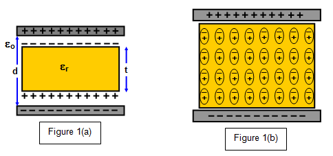
Two conductive plates sandwiching a dielectric material which prevents charge carriers from crossing, instead letting them accrue on the terminal (subsequently leaving an electron void on the positive terminal.) With a primitive understanding of electric fields, it should be natural to understand that an electric field is thus formed due to the voltage differential and furthermore the field is maintained as a consequence of the dielectric's constituents becoming polarised.
AC domain
Things become invariably more interesting when adding a frequency component to the voltage. By adding a frequency I mean the voltage is periodic over time, whether that is through being sinusoidal (most typical,) or any other periodic configuration (rectangular, triangular, sawtooth, etc..) AC is generally the easiest to produce mechanically (through AC generators,) and it has a lot of properties that make it pertinent in analog circuitry by the sheer property of being alternating and periodic.
However, typical circuit components suddenly exhibit more interesting behaviour when under AC. All the sudden we have impedance and reactance