Introduction
So, after deciding to undertake another technically challenging project, I have expanded my domain of knowledge in embedded development which I would love to share. I've left with far more questions regarding the idiosyncrasies and inner-workings of everything related, but I guess that's about on-par for such an expansive field which connects software development with electrical engineering.
What do I want to achieve in simple terms? Streaming audio data to a speaker over USART. It feels like a great way to collate everything learned thus far into a concrete project which may have an actual use. For now, unfortunately, the story's ending is tragic, since I could not get a satisfactory result, and what's perhaps worse is that I don't fully understand why I couldn't, although I have some theories.
What we're dealing with--physically
There are two main physical components, one of which has been covered in prior discussions:
1. TPA2005D1 mono-audio 250kHz class-D amplifier
From how I understand it, it's a highly-efficient audio amplifier which takes our audio signal and amplifies it to be capable of driving a speaker, given the defined electrical characteristics, which are that it can deliver up to 1.4W into a speaker with $8\Omega$ impedance.
As we'll discover, the 'H7 has a built-in digital-analog converter (DAC), so we could somehow theoretically drive audio signals straight to a speaker, but from how I understand it, the DAC output pins aren't intended to drive current (just voltage,) so we would not be able to even drive a remotely sufficient current to produce audible sound.
Hence, we need an amplifier to supply the current for the appropriate impedance relative to our 3.3/5V lines.
2. CP2102 USB-to-TTL UART module
Hopefully self-explanatory, we'll be solely using receiver-mode (Rx) to receive data from the host (a little script to stream audio data on my PC.)
3. The STM32H723ZG as our core microcontroller, it seems to feature every peripheral that a hobbyist might need for literally any project, and though more expensive than the 'F1/4 family, typically by an order of magnitude, it's certainly the best choice for learning.
4. ST-Link v2, for debugging & flashing operations. I won't be semi-hosting this time around, so it's back to good old gdb and bkpt instrumentation.
5. A speaker driver, anything with exposed terminals to which the amplifier can be connected. The only important specifications are the speaker's impedance and power since they must be suitable for the selected amplifier, though I imagine it'd be hard to find speakers with lower power ratings than these small-form amplifiers.
Only naturally, this isn't all that's required, since the TPA2005D1 will need external circuitry to make sure our signal is integral--since unsurprisingly AC and audio signals are complicated. I'm starting to understand why good speakers and AVRs are so expensive.
Note: It would be wise to implement transmission on USART for printf-debugging on the host-side. Unfortunately, I'm not wise--but, I do have the youthful energy necessary to spend time debugging through more primitive means (my ever-faithful gdb.)
Looking at other amplifiers
Another product I looked at is the MAX98306 stereo class-D amplifier, capable of driving 1.7-to-3.7W loads at 8$\Omega \to 3\Omega$ impedance respectively. Marginally more powerful than the TPA2005D1, and seemingly more ubiquitous for purchase. I also broke my TPA2005D1, so this suggestion is merely a result of my mechanical incompetency in soldering.
Where do we start?
As with everything else before, we forego the CMSIS hardware abstraction layer (HAL,) because honestly it's ugly, and most importantly it hides the beauty in becoming intimate with the architecture, whether through toiling with benign documentation errata, or most importantly through having lightbulb moments where the system architecture starts to piece together in your mental understanding.
So, we start with the bare-metal and write our own minimal HAL. From its initial design, we can continue in whichever direction we wish. I wish to continue in the following direction: 1. Configure/enable USART for receiving audio data 2. Configure/enable the DAC for reading the audio data and transmitting it on the allotted GPIO pins 3. Stream audio data from my PC over the CP2102 module
This is a painfully simplified itinerary, so for completeness here is the technical description of what we need to achieve:
- Enable our peripheral clocks (
GPIO,TIM,DAC,USARTandDMA) - Initialise, configure, and enable our GPIO pins for USART receival and DAC analog output to the TPA2005D1.
- Configure two direct-memory access (DMA) streams:
- USART $\to$ Memory: continuously read audio data from the peripheral into a static memory buffer, clocked at the baud-rate
- Memory $\to$ DAC: continuously read audio data from the static memory buffer into the DAC data-holding registers (DHR) pending their output on the pin, clocked at the audio sample rate
- Ensure these DMA streams are multiplexed against the appropriate triggers (in
DMAMUX:) we want DMA requests to be made for the correct stream when the appropriate trigger is detected, e.g., USART data received, timer overflows. - Initialise, configure, and enable USART in receiver-mode at a baud-rate sufficient to ensure data integrity and tolerable real-time latency with respect to the audio sample rate. USART also has specific configuration considerations when running in DMA mode.
- Initialise, configure, and enable our timer which will drive the DAC at the audio sample rate so that it may create DMA requests to transfer the next audio sample to the DHR at the appropriate frequency.
- Initialise, configure, and enable the DAC to be triggered by the relevant timer we've assigned in the previous step.
At a high-level, this is a decent description of what needs to be done to achieve a minimal-working example in theory, but even each step listed has its own set of considerations. A lot of new terms and ideas are introduced, so it would be best to start from an architectural view.
How do we plan on streaming audio data?
Let me introduce pulse-code modulated (PCM) data, a fairly simple format in theory. PCM stores analog audio samples by uniformly quantising their amplitude into a fixed-width data-type, i.e. a un/signed 8/16/32-bit integer. Naturally, with lower resolution data-types, we lose some depth in the signal, and by the nature of quantisation, the signal--if we were to transmit it directly--would be stepped with rough edges (enter the ever-so humble capacitor.)
For my application, I intended to use the simplest configuration consisting of 8-bit unsigned PCM audio data at 22.05kHz, into which we can convert common media formats like MP3 into simply with ffmpeg.
Note that our audio sample rate creates a dependency on how fast our USART transmitter/receiver pair must be, so being realistic here will likely save some headaches when configuring USART later.
Then, given that we have our audio streaming data format, we need to figure out the logistics of how we'll get it to the 'H7 from the PC. This is fairly trivial, so here's the script:
import serial

SERIAL_BAUD_RATE = 115200
SAMPLE_BUFFER_SIZE = 256
pcm_fd = open(".\\music.pcm", "rb")

with serial.Serial("COM6", SERIAL_BAUD_RATE) as conn:
  while True:
    pcm_data = pcm_fd.read(SAMPLE_BUFFER_SIZE)
    if not pcm_data:
      break
    conn.write(pcm_data)

pcm_fd.close()
And thus the concept that we should likely buffer audio data is introduced, it's more likely that we'll run into latency issues if we stream byte-for-byte from USART to the DHR because of all the overhead necessary to send a single byte. Consider that we must be sampling a byte every $1 / f$ seconds from USART to DHR [to DOR]$^1$, we can parametrise buffer size by the time-length of audio data that it can store, e.g. a 256-byte buffer at 22.05kHz stores 11.6ms of audio.
What's the most cost-effective buffer-size to minimise both latency and storage? Whatever you can afford, likely. Ideally USART should be capable of receiving at a rate exceeding the audio sample rate, so that once the audio buffer is drained, it may be refilled without audible distortion (see next section.) In theory, for 22.05kHz, the DAC will be requesting a sample every $50\mu s$, and assuming our baud-rate is 460,800 (no parity bits) we will transmit a byte every $20\mu s$.
$^1$ The DAC enables several ways for you to input data, whether it's 8/12-bit left or right-aligned, so there's an internal conversion step it undertakes resulting into the data-output register (DOR) where the output voltage-level is stored
Double-buffering to minimise auditory distortions
The initial idea I had, although not considered in the itinerary, was that we would store two audio buffers, essentially one hot buffer (ready for the DAC) and one pending (either filling/filled by USART.) This would prevent the issue that single-buffering could cause wherein the DAC has drained the audio buffer, and the latent period between the USART refilling the audio buffer with the next samples causes an auditory distortion or lag on the speaker as no new audio data is available.
The latent period would be characterised by the baud-rate, e.g. a 460,800 baud-rate refilling a 256-byte buffer would ideally take 5ms, which is otherwise time spent by the speaker idling. It does come to mind that perhaps the DAC could keep sampling the audio buffer as it is refilled per-byte, but this would introduce the potential for race-conditions/desynchronisation which would be painfully horrible to debug.
Double-buffering removes the latent period's time dependency on the baud-rate, and instead places it on how long it takes to swap the memory buffers. Obviously, the baud-rate is still constrained insofar as that the second buffer must be ready by the time the hot buffer is drained, otherwise additional latency is compounded on top of the swapping routine.
The benefit is that DMA double-buffer swap operations (typically clocked by the system clock) take one clock cycle, and so are effectively instant, since they're operating under a MHz range, compared to our insignificant kHz sampling rates. For reference, if our system clock is 400MHz, we would need to sample at 400MHz at somewhere around 4Gbps baud-rate for the swap operation to even be on the same order of magnitude.
Receiver/transmitter synchronisation: avoiding receiving too much data
Given the previous configuration: 460,800 baud-rate with a 256-byte double audio buffer, and 22.05kHz sampling rate. Who's to say that we aren't receiving data from the host at a faster rate than our DAC may play it? We don't want to overwrite yet-unprocessed audio samples with newer ones. To make it clearly apparent, a 460,800 baud-rate means we receive 57,600 bytes/second ($17\mu s$ per byte received, 4ms per buffer,) and our 22.05kHz sample-rate--which we may also normalise to the buffer-size--means we process a buffer every 11.6ms. We have a 7ms margin where USART should be waiting for the DAC to mark a buffer as processed.
Let there be flow-control--two forms of it. We can decide to send control codes to the host indicating it should pause for a moment (XOFF) or continue sending more audio data (XON,) but particularly with audio data we should wish to avoid this, since each audio sample may inadvertently itself be a control code. So, we only have hardware flow-control, which means we need a couple more hardware lines on our adapter, namely: request-to-send (RTS) and clear-to-send (CTS.) The host drives the RTS line low/high depending on whether it has audio data to send, and conversely our 'H7 will de/assert CTS depending on whether it is ready to receive more data. So, we just simply assert CTS when the DAC indicates it has processed a buffer so that we may repopulate it, and when RTS is deasserted we may assume that the audio transmission is completed and we may begin finalisation if we so wish.
An interesting alternative is to have a baud/sample-rate configuration which is perfectly equivalent, so that, for example, the DAC processes a buffer every 10ms, and USART populates a buffer every 10ms. Obviously, this is practically infeasible when working with hardware that isn't really real-time capable on both Tx/Rx sides since jitter and lag means the DAC will try to sample data that is not yet populated, or with enough time USART will start to overwrite samples that are yet to be processed. Anyways, in an ideal world we would have no need for buffering, since we would just choose the perfect baud-rate and stream straight from peripheral-to-peripheral.
A brief introduction to DMA
The main driving force enabling us to facilitate transfers from USART to the DAC is DMA. There's four types of DMA on the 'H7:
1. DMA: the standard interface, including two controllers DMA1 and DMA2 which cover the interfaces for regular and mostly low-power peripherals (LPTIM, LPUART, etc.) respectively. Each controller has 8 streams to which requests can be configured.
2. BDMA: basic DMA, I'm not too sure how it's more "basic" than regular DMA beside the fact it calls streams channels, and it seems to only service low-power peripherals through DMAMUX.
3. MDMA: master DMA, I haven't had any need to look at this controller, but it seems to be a superset of regular DMA with even more features to make life easier.
4. DMA2D: DMA, but with colours; seems likely to be essential for any application that draws to framebuffers.
The operation of DMA is fairly simple though quintessential. For USART we need to trigger a peripheral-to-memory DMA transfer on each USART receive, observe the following figure:

USART will generate the DMA request on its own accord when each block arrives, so all we need is to have an interrupt handler to be signaled when the transfer is completed. Keep in mind that while we're operating under real-time conditions, we should never need to pause streaming to allow the DAC or other components to catch up: USART will always be streaming into the buffer.
As for the DAC, the generation of DMA requests which transfer data from the audio sampling buffers into the DHRs will be driven by a timer, essentially acting as a clock, which will run at the prescribed audio sampling rate (22.05kHz in the example case.) The triggers are selectable as given by the following table:
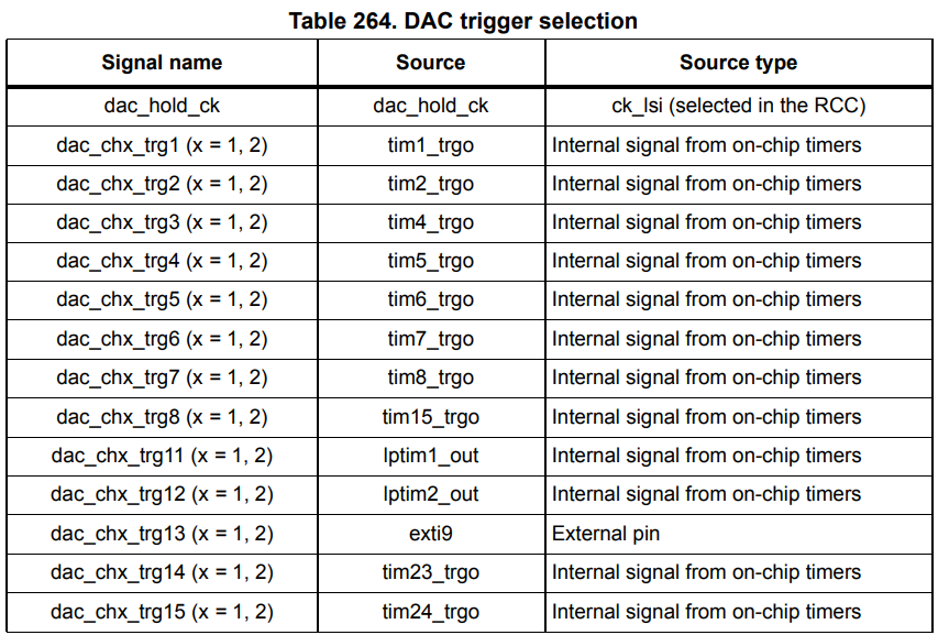
--and subsequently selected by the TSELx DAC registers. The corresponding timer register MMS (master mode selection) must be set to configure a timer count overflow (update event) as the trigger output, which means we will trigger the DMA transfer request against a configurable frequency determined by the auto-reload/pre-scaler timer registers.
Be careful where you're reading and writing memory from/to
Take a short glimpse at the 'H7 bus matrix:
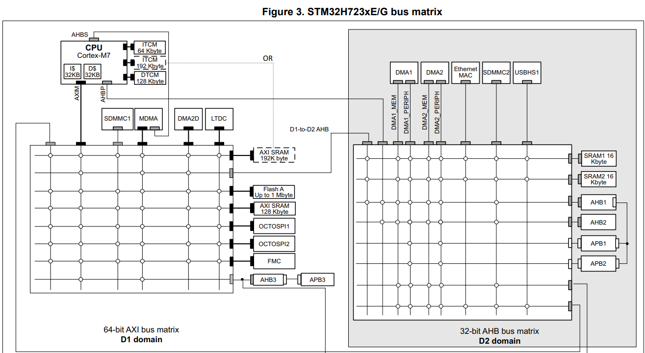
Note that the DMA1 bus cannot access certain peripherals, such as the data tightly-coupled memory (DTCM) region, which starts at 0x20000000, typically where you put all data that you want to have very quick read/write access to. Since I migrated from the 'F1 and 'F4, the legacy HAL code had been agnostic to any bus access limitations, so every time the DMA request tried to transfer data from audio buffers into DHR, a transfer error occurred which was eternally puzzling.
Placing the audio buffers in AXI SRAM was the simplest solution, related StackExchange question I wrote here.
Choosing, and configuring which timer will drive our DAC
After some minor comprehensive analysis of the difference between the similarly grouped general-purpose timers which have some crucial functional differences that somebody may desire, it became evident that there's no purpose in using timers with more extensive capabilities, and as long as the timer is capable of producing a 22.05kHz clock with minimal jitter it should suffice. So, I chose to use the basic timer group, since it also allows selection of the trigger output mode necessary for interfacing with the DAC. The only problem left is the selection of the auto-reload/pre-scaler values which when enabled will generate overflow/update events at a desired frequency.
Note: The auto-reload register (ARR) refers to the value the timer will restart counting down/up from when it overflows. The pre-scaler (PSC) register sets the value by which the timer's actual clock is divided.
Calculating the update frequency
Our update frequency is the rate at which the timer will overflow, contextually adjacent to our audio sampling rate. Absorb the given formula for a moment: --and: Working from $f_\text{TIMx}$, this obscure constraint on $n$ is derived from the fact that the timer clock frequency may be either equal to the bus' clock which drives the timer, or double its frequency:
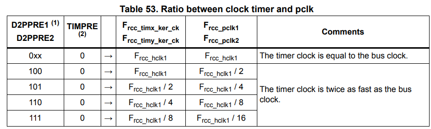
Deriving $f_\text{HCLK}$ is a separate exercise covered in prior discussions which simply involves taking a look at the product datasheet, and calculating the derived bus clock frequencies using the pre-scalers given in the RCC register.
So, then we could let $f_\text{OVERFLOW} = 22050$, and work our way backwards determining a set of constraints on ARR and PSC including the fact they're 16-bit registers--but that's not really practical, and albeit as a mental exercise it's interesting, there is a simpler solution. Let PSC be zero, and we just have: From what I've gathered, it seems better to have a smaller pre-scaler (and thus larger auto-reload value) so that our timer is more granularly clocked. Intuition seems to agree: if we have a wider auto-reload value, then it's probably going to be more accurate if we want to detect half-transfers, or anything of the likes. We're not checking for half-transfers from memory-to-DAC, so it likely doesn't matter for such a simple application, but nonetheless a worthwhile consideration to reduce jitter.
Aside on voltage scaling and overclocking
A small thing that tripped me up when I was trying to calculate the system clock for the timers is that the 'H7 has tuning parameters to enable core overclocking, this being under the PWR.D3CR.VOS register: four voltage scaling (VOS) levels from 0 to 3.
These don't change the core frequency by themselves, however they enable the capability to then subsequently increase the frequency, constrained per the characteristics laid out in the datasheet. So, core frequency calculation is agnostic to VOS, unless the frequency is also reconfigured, which then should mean you're using PLL, for which you should have the appropriate calculations.
Configuring the timer to work with the DAC
So, we have our timer configured with the correct pre-scaler and auto-reload values to produce a 22.05kHz update frequency, CR2.MMS is set to $010_2$ so that updates create an internal trigger output which causes the DAC to convert the data stored in the DHR into a voltage-level available to the amplifier.
Our DAC has CR.TSEL1 set to the corresponding trigger output for our specific timer, and CR.DMAEN1 is enabled so that a DMA request is created after each time the DHR is converted, as described:
When an external trigger (but not a software trigger) occurs while the DMAENx bit
is set, the value of the DAC_DHRx register is transferred into the DAC_DORx
register when the transfer is complete, and a DMA request is generated.
So, our DMA request will have the responsibility of moving the next available audio sample into the DHR, otherwise stalling if transmission is complete, or for some reason the buffer(s) aren't ready. Take a look at the following operational rough-sketch:
.png) Although not fully cohesive nor comprehensive, it describes the rough operation of how streaming should work with double-buffering. The application main-loop essentially looks like this:
1. Configure peripherals, zero-initialise two audio buffers in AXI SRAM
2. Enable USART receiving with double-buffering on DMA pointed to both buffers, interrupt enabled for full transmission. Configure RTS/CTS.
- On full-transmission where we've received a full audio buffer, if the DAC has indicated it has not processed its current buffer yet, de-assert CTS so that we don't receive more, and set the inactive DAC DMA memory address to the new buffer
- If RTS is deasserted, then transmission has completed and we may disable all the peripherals
3. Enable DAC and TIM6, configure DAC DMA to be circular and double-buffered, pointing both addresses to the same buffer initially, and configure TIM6 to trigger the DMA request at a 22.05kHz rate, enabling the full-transmission interrupt
- Once the transmission is complete, set a flag to indicate we've processed the ready-buffer, and re-assert CTS
Note that these steps deviate from the flowchart above since, over the course of a couple weeks I've realised it's a little bit more complicated than that and yet simpler at the same time.
Although not fully cohesive nor comprehensive, it describes the rough operation of how streaming should work with double-buffering. The application main-loop essentially looks like this:
1. Configure peripherals, zero-initialise two audio buffers in AXI SRAM
2. Enable USART receiving with double-buffering on DMA pointed to both buffers, interrupt enabled for full transmission. Configure RTS/CTS.
- On full-transmission where we've received a full audio buffer, if the DAC has indicated it has not processed its current buffer yet, de-assert CTS so that we don't receive more, and set the inactive DAC DMA memory address to the new buffer
- If RTS is deasserted, then transmission has completed and we may disable all the peripherals
3. Enable DAC and TIM6, configure DAC DMA to be circular and double-buffered, pointing both addresses to the same buffer initially, and configure TIM6 to trigger the DMA request at a 22.05kHz rate, enabling the full-transmission interrupt
- Once the transmission is complete, set a flag to indicate we've processed the ready-buffer, and re-assert CTS
Note that these steps deviate from the flowchart above since, over the course of a couple weeks I've realised it's a little bit more complicated than that and yet simpler at the same time.
Conclusion & take-aways
A lot of upsets occurred along the journey, the repository as it stands in its non-working state exists here. Unfortunately, I mishandled the amplifier board and broke some of the connection points, and likely messed up in connecting the resistor-capacitor network, and furthermore some of the more theoretical clarity came subsequent to these events, meaning I couldn't test out new ideas without waiting another couple weeks for the delivery of a new amplifier. I was quite demotivated when I'd realised after I'd written half of this discussion that I'd failed to consider synchronisation concerns (now detailed under How do we plan on streaming audio data?) and I had let it rest upon my mind as something heavier than it was in reality.
Even now, there's quite a lot that remains undocumented simply because working through all the pedantic details becomes complicated in its own right when your interest is rooted in understanding the fundamental principles behind concepts and their mechanisms. However, I gratefully appreciate that I've left this endeavour a better developer, with an enhanced intuition on problem-solving, research, and analysis in this domain.
I will certainly try to find time to revisit this idea when I can acquisition another amplifier, since even envisioning the gratification of finally being able to play a song, even in the lowest quality, through devices I joined together with mere hopes and dreams, is in itself satisfying to imagine.
In short, always read the manual more than you'd ever be able to remember, plan ahead with just the crude ideas that you think you understand, and critically spend time trying to find holes in your plans, no matter if those holes are too deep to fill.